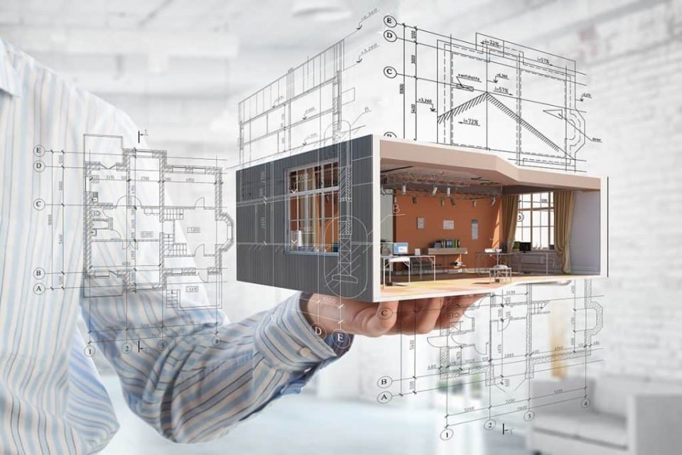
From historical times megastructures have been made all around the world, and this has been possible with sheer planning and accurate mathematics. When the planning and mathematics were drawn on paper, it turned out to be known as architectural drawings in modern times. Architectural drawings are used for numerous purposes, i.e., to develop an idea in a proposal with coherency, to convey ideas and concepts easily, to persuade the customers about the design by pictorial representation, and to help the contractor in assistance in building the structure . best architects in jaipur
Architectural Drawings are made under some set rules and universally accepted conventions. This is done so that the drawings can be read and understood easily. In the beginning, the drawing was made on sheets with ink, but now, after the advancements in technology, they have been made using the software . for more check https://www.skywalkdesigns.in/
Scale:
Structures are so enormous that representing it on paper or on software in the same size is not possible. To tackle this problem, some conventional calculations are available which define a scale for the structure so that it can be represented on paper without any loss of details or information. Scale for an architectural drawing is chosen such that the buildings can fit on the sheet with all the details properly displayed.
What are the views in which a structure can be studied?
Views are the directions from which a structure is studied.
FLOOR PLAN:
This is the most fundamental view of a structure. This is the view from above in which the spaces in between and the arrangement is shown clearly. Basically, this is the horizontal section cut at a particular level, showing doors, windows, and other features of that structure at that level.
SITE PLAN:
A site plan is the detailed pictorial representation of the particular area where the structure has to be built. It gives a full overview of the travel ways, parking, sewers, drainage, water supply, etc.
ELEVATION:
It is the view seen from one side of the building. Technically, it is the orthographic projection of the structure, which gives the external appearance of the building.
CROSS SECTION:
It represents the vertical section of a structure. The cross-sectional drawing gives the view of the building when it is cut through vertically. As the floor plan gives a horizontal section, the cross-section gives the vertical section of the particular structure.
ISOMETRIC AND AXONOMETRIC PROJECTIONS:
- An isometric uses a plan with the grid at 30 degrees from the horizontal plane in both directions.
- An axonometric use a plan with a grid at 45 degrees, which gives the horizontal orthogonal view to the plan. The builder can directly work through this plan.
Architectural Perspectives:
Perspective is a representation of the 2-D plane that we perceive through our eyes. It is the view from a particular point that is fixed in space such that the lines leading away appear to converge at a point.
We can conclude that these are some of the criteria which are included under the conventions of architectural drawings.

